2D: Continued development of the GPIT (GV Pod Inlet Test) Project
The FAA certified HIMIL inlet is the standard design for chemical measurements deployed on the NCAR/NSF GV aircraft. The design was adapted for chemistry measurements for the DC3 mission by ACOM (ACD at the time) and these inlets have since been used successfully on subsequent missions. However, very reactive gases such as halogen oxides, radicals, or compounds that typically exhibit strong inlet wall effects such as nitric acid or ammonia, have been challenging to measure on board the GV. The windows of the GV cannot be equipped with sampling apertures. Existing sampling apertures are located on the top of the fuselage or belly of the GV aircraft. As a result, minimum inlet line lengths are at least several feet (or longer depending on the rack station), and often require bends in the sample flow. We therefore explored the suitability of the GV wing pod for measurements of highly reactive gases. The pods are attractive since they allow a gas inlet at the tip and are not fully subscribed with instrumentation at this time. In 2017, we developed and deployed the Gulfstream-V Pod Inlet Test (GPIT). GPIT was designed to function as a test facility rather than as the front end of a practical analytical instrument system. The focus of the 2017 design effort was to experiment with a large bore centerline inlet assembly with a high conductance lateral exhaust port.
The goal of the continued effort to develop a Gulfstream Wingpod Inlet design during FY2018 was to transform the 2017 GPIT facility into a practical front end for a pod-based instrument. In light of our success in the 2017 flights, we decided to preserve the existing design of the leading edge inlet and exhaust structures without modification. During the ARISTO-2017 flights, it became clear that the growth of the boundary layer within the inlet is the dominant component of wall contamination within the inlet. In order to minimize the boundary layer growth we need to maintain high axial sample flow velocity, while minimizing inlet length. Previous research in this field has focused on slowing of the flow before injecting the sample into an instrument (Eisele et al, 1999). In order to predict accurately the boundary layer growth as a function of flow rate, we have collaborated with Clarkson University (S. Dhaniyala) to model the airflow using Computational Fluid Dynamics (CFD). By analyzing both the flow path and trace chemical deposition rates within the inlet we have designed a system which will not only slow down the flow as needed, but will also minimize the amount of target compound deposition on the walls of the inlet.
The remainder of the 2018 design effort was to redesign the interior of the inlet assembly to provide the pressure and flow control mechanisms required for effective sub-sampling and bypassing flows within the system. Most instruments typically need a maximum sample flow of a few to a few 10s of liters per minute (lpm). In order for the inlet to be effective, the instrument must subsample the main gas stream (100s of lpm) from the non-contaminated core flow at the center of the main gas stream. Early in the design process we identified the use of multiple nested ducts as the most flexible way to subsample the central core of the main flow. The concept of nested ducts is illustrated in Figure 1:
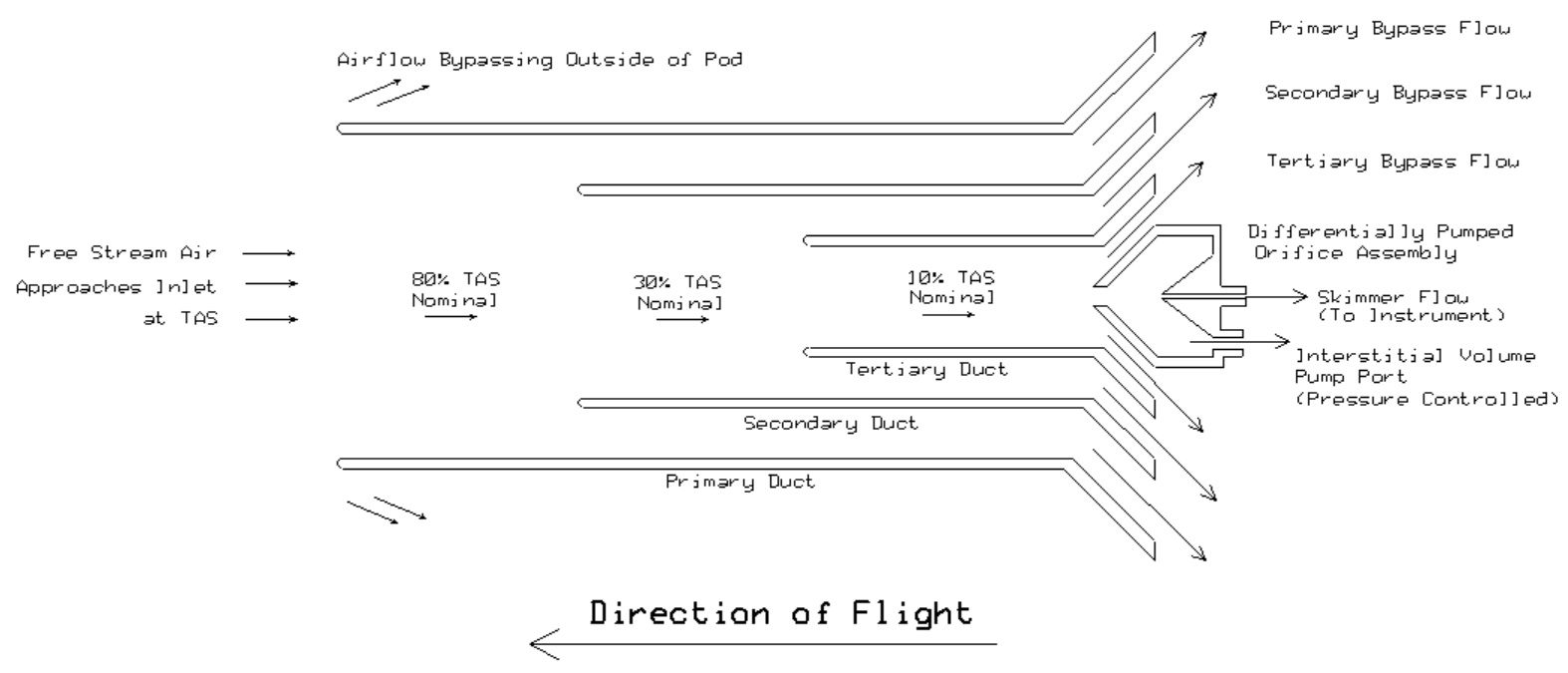
The inlet entrance on the leading edge of the pod is the same 3” ID inlet used in the 2017 flights. The interior of the leading edge blends into the 3” diameter primary inlet duct. During flight, a parcel of free-stream air will approach the inlet at the “True Air Speed” or TAS of the aircraft. For the Gulfstream V a typical TAS would be 150-250 m/sec. Once the parcel of air enters the primary inlet, it is divided into the primary bypass flow and the secondary inlet flow. The secondary inlet flow is further split into a secondary bypass flow and a tertiary inlet flow. The tertiary Inlet flow is split into the tertiary bypass flow and the differentially pumped orifice flow, as shown in Figure 2.
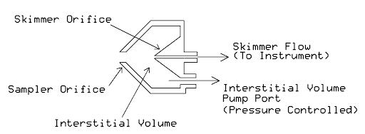
The differentially pumped orifice assembly, pictured above, represents the transition from the inlet to user supplied instrument. In the above situation, the volume between the two orifices is maintained at a constant, sub-ambient pressure (~100 mbar). The orifice to the left (Sampler Orifice) limits the maximum ambient flow into a pressure controlled interstitial volume. The orifice to the right (Skimmer Orifice) limits the flow into the analysis system. The flow through the Skimmer Orifice is determined only by the interstitial volume pressure (IVP), if the internal instrument pressure downstream is at least half of the IVP and the flow through the skimmer orifice into the instrument will remain constant, regardless of aircraft altitude.
It should be noted that there are several possible variations on how to best regulate the pressure of a sample flow prior to entering an airborne instrument. We have experience with the differentially pumped orifice technique, and found it to be effective in the past for instruments which do not allow a flow controller or other devices with a large surface area in the flow path. Most gas phase chemistry instruments including CIMS, PTR-MS and chemiluminescence instruments should work well using this technique. Other techniques may be better suited to other measurement methodologies. We will design the sample pickoff portion of the inlet in a modular and adaptable fashion so it can be interfaced to any user supplied instrument system.
A flow diverter assembly was designed to split and exhaust the necessary bypass flows for the primary and secondary inlet ducts while minimizing flow resistance. The assembly is mounted as close to the leading edge inlet as possible in order to keep all inlet lengths to a minimum and thus avoid wall losses in the tertiary inlet duct. A cross section view of the flow diverter is shown in Figure 3.
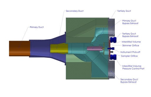
The shape of the flow diverter assembly has to be as compact as possible to allow the shortest possible tertiary inlet length but it also needs to allow for the lowest possible resistance to the flow path to maximize the primary and secondary bypass flows. Therefore, NCAR partnered with Professor Suresh Dhaniyala and his Computational Fluid Dynamics (CFD) Team at Clarkson University to theoretically optimize the design. Our first step in creating the inlet flow model was to run a CFD analysis of the results of the 2017 flight campaign. By using the known inlet geometry and flight sensor data we were able to verify the model validity and define the approximate flow boundary conditions observed during our 2017 flights. Once the flow boundary conditions were established, we used that information to derive a predictive model of flow performance through the 2018 inlet design. The team at Clarkson utilized ANSYS software to analyze our mechanical model for both flow efficiency and trace chemical deposition rate. This collaboration enabled the present design of the diverter geometry. By iterating between the mechanical and fluid models we determined the optimal compromise between the overall size of the diverter assembly while maximizing the flow conductance and minimize trace chemical deposition rate.
Our original goal was to test the revised Gulfstream Wingpod Inlet during the Fall of 2018. The inlet was scheduled to be deployed on the Gulfstream-V as part of the ARISTO-2018 deployment. The cancellation of ARISTO 2018 did not allow us to conduct the test flights
Going forward, we will complete the existing design/fabrication cycle prior to the end of FY2019. We will perform limited bench testing of the hardware/software to ensure basic operation of all of the required subsystems. It is our goal to complete the inlet testing during the next possible ARISTO opportunity on the Gulfstream-V. Testing the fully functional inlet design (with a wall effect tracer study) is the next step prior to integrating the inlet with any new NCAR or University based instrument system.
Contact
Please direct questions/comments about this page to:
Carl Drews
NSF NCAR | Research IT | ACOM